Here is a design for a DC motor speed control featuring:
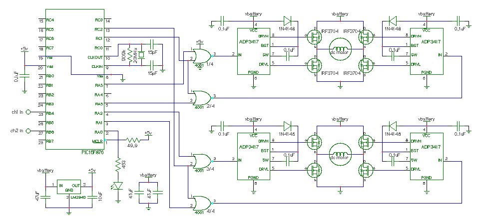
This is the schematic for the design:
Theory of operation:
A Microchip PIC16F876 interfaces to a standard 2 channel RC receiver. The PIC device mixes the 2 channels together, and generates 2 PWM signals, and 4 direction signals. 4 4001 NOR gates combine the direction and PWM signals to drive Analog Devices ADP3417 MOSFET hi-lo drivers. The ADP3417's drive the IRF3704 MOSFET devices which are configured in an H-bridge configuration. Depending on each motors direction, one side of the H-bridge gets the PWM, while the other side is held constant (hi=off lo=on).
An LM2940 low headroom voltage regulator generates a clean 5 volt supply to run the 4001, the PIC and to provide the BEC function for the RC receiver.
PIC source code
The PIC device was programmed in C with a lot of in-line assembly. The code
was compiled into hex code and loaded onto the PIC device using the Microchip
PIC programmer. Source code development was done under Linux.
Here is the C source code.
Here is the hex code.
Here is the Makefile.
About the components:
The IRF3704 power MOSFET device was chosen for it's large current capacity, low on resistance, and low gate threshold voltage. This device also has a large built in reverse P-N junction diode capable of large currents, thus eliminating the need for external fly-back diodes. (datasheet)
The ADP3417 MOSFET driver was ideal for this application. It operates with very low supply voltages, includes overlap protection (to make sure both hi and lo devices are never on at the same time), performs the bootstrap operation for the hi MOSFET, and uses very little supply current. (datasheet)
The LM2940 regulator was chosen for it's low dropout voltage (0.5v at 1.0amp load) features reverse battery protection, has a short circuit current limit, and also has thermal overload protection. (datasheet)
Finally the PIC16F876 was chosen for it's 2 PWM outputs and large program space. This made the software easy to implement. A smaller PIC could have been used, but would make software development harder. (datasheet)
Here are some pictures of the project:

The top side of the board. |
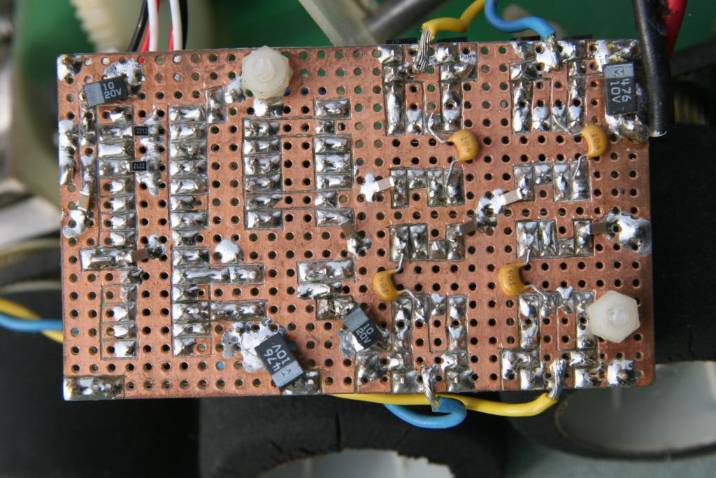
The bottom side of the board. Note that all copper that isn't being used for routing signals is part of the ground plane. |
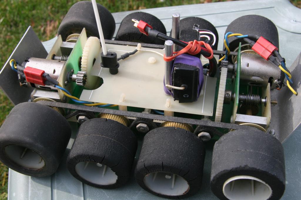
The RC "tank" that uses the speed control. The speed control sits upsidown in the center of the tank. |
Notes:
To ease my job building the circuit board, I ordered all of the parts in a large DIP format. I even ordered a large format crystal. The ADP3417 was only available in a small SOIC package, but I soldered it onto a DIP socket anyway. A much smaller circuit board could be built by using smaller SOIC packages for all of the components.
The MOSFET devices are not heatsinked. This is a bad idea, but the DC motors I am using don't draw much current (maybe 5 amps max, 0.5 amps typ), so the MOSFETs don't get hot.