Here is a design for a 500 watt bench power supply featuring:
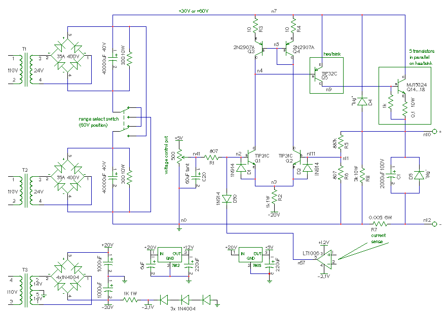
This is the schematic for the design:
Theory of operation:
The supply is a basic linear type, utilizing large NPN devices (Q14 through Q18) connected in parallel to regulate the output voltage. The collectors of the output devices (sometimes called pass transistors) are connected to a 30 volt or 60 volt filtered source, and the emitters are connected to the output. These transistors act like variable resistors that "throw away" the excess voltage between the 30 or 60 volt source and the output. Under worst case conditions the output devices must be able to dissapate 600 watts of power and thus require large heat sinks.
Two transformers (T1 and T2) are connected to 110 volt AC and output 24 volt AC sinewaves. These reduced voltage sinewaves are rectified by full bridge diodes, and then filtered by 40000uF caps. The output of these caps are connected in parallel or series to set the 25 or 50 volt operating mode.
The input section is a differential pair (Q1 and Q2) that together with the current mirror (Q3 and Q4) perform the differential to single ended conversion required for the feedback loop. Resistor R2 sets the bias current for the input section. The PNP device Q5 ties it all together, amplifying the current from the input section to drive the bases of the output devices.
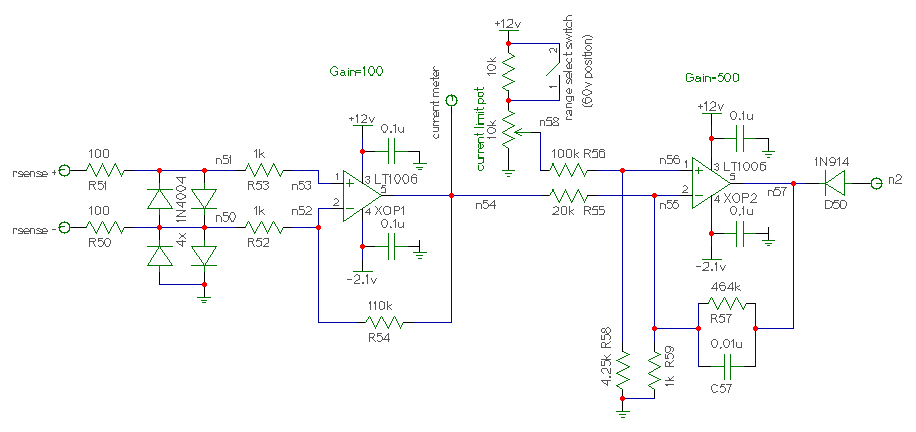
Current limiting is done by sensing the voltage drop across R7 (with opamp XOP1) amplifying that voltage with XOP2 and pulling down on the positive input node (N2) through diode D50 if the sensed current is greater than set by the current limit pot.
To power the opamps, and provide a negative voltage to supply some of the curcuitry, T3, the 4 1N4004 diodes, and two 1000uF caps are used.
Diodes D1, D2, D4 and D5 are all in place to protect the circuit from misbehaved loads.
The maximum regulated output of the supply will be a few volts lower than the 30 (or 60) volt source due to the diode drops and staturation voltage in the feedback loop transistors. This will limit the maximum regulated output to about 25 (or 50) volts.
This is the current limiting circuit:
Here are some pictures of the supply.
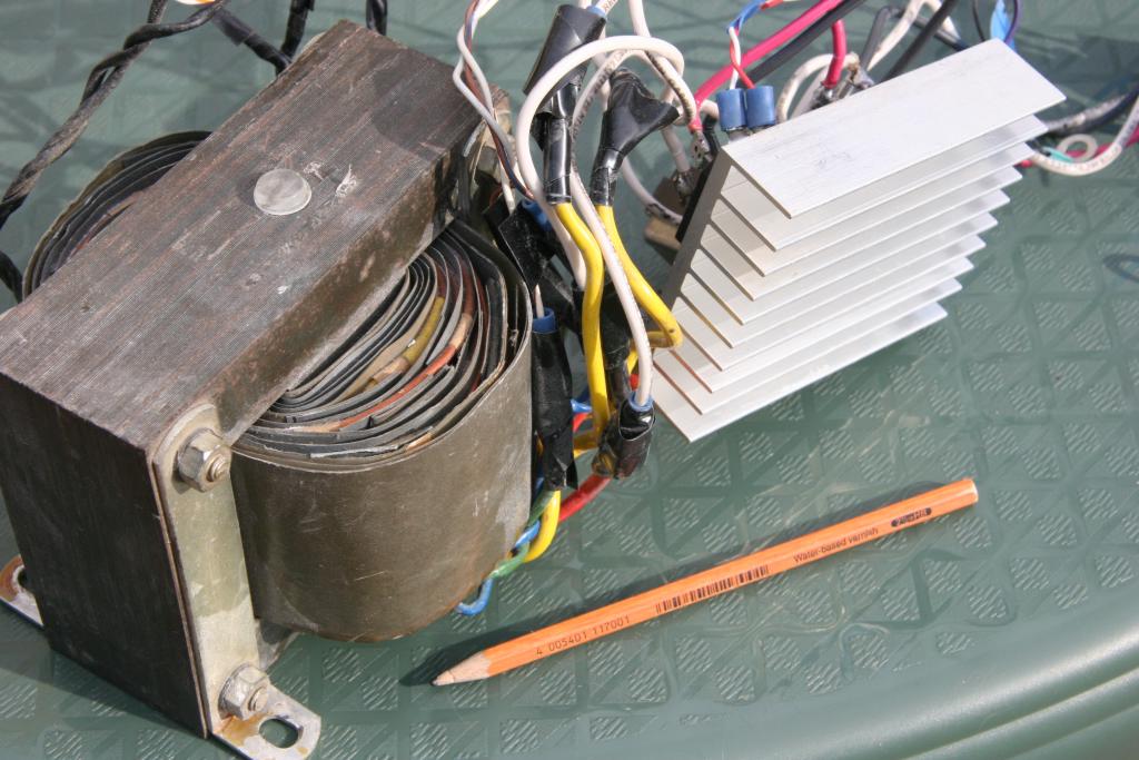
The transformer. This contains all the windings (T1, T2, and T3). |
Rough component placement. The empty spot on the left is for the transformer. Note the large heatsinks. |
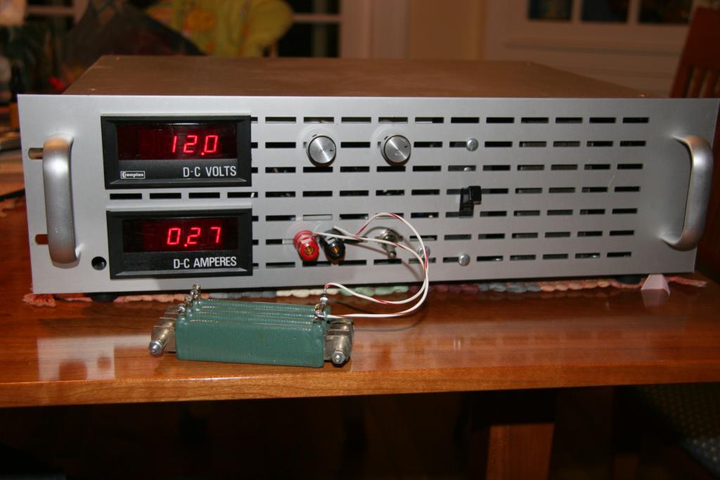
The front panel showing the controls. |

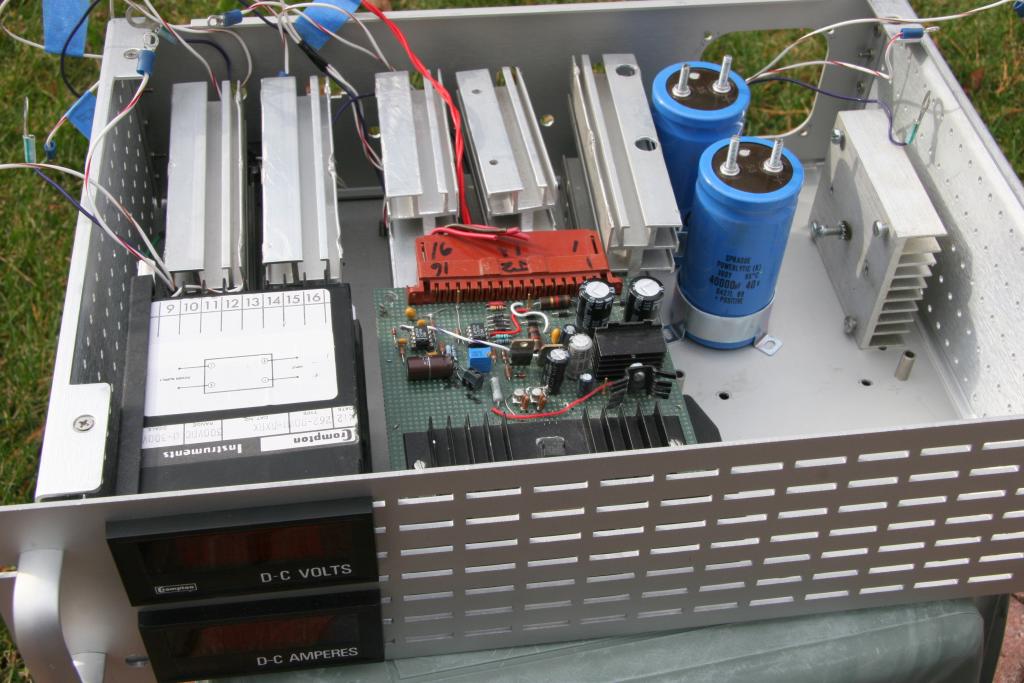
Inside the finished supply. |